L'Hexapod: Where are we?
This article was previously published on lhexapod.com as part of my journey of discovery into robotics and embedded assembly programming. A full index of these articles can be found here.
Once the servo controller code was feature complete I switched to looking at the hardware side of things and thinking about the next stage, the servo sequencing.
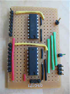
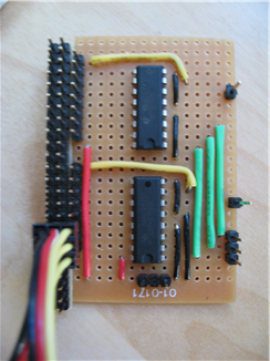
From a hardware point of view I had several things to work on. Firstly I needed to get the servo controller and I/O multiplexor chips off of a breadboard and onto something a little more permanent. Since I still find building things with perfboard a little hard I decided to build the controller itself on one board and build separate daughter boards for the I/O multiplexing. This should mean that I can replace the parts separately as long as the connections required remain the same. I decided that each I/O daughter board could contain 2 CD74HCT238E’s with some header pins for each of the 16 output channels, 3 pins for the address selection lines and 2 more for the signal lines. I deliberately left off the power and ground pins for the servos as these really didn’t work well on the perfboard. The power and ground pins are connected in one direction and the IC to servo control connections are in another direction; without some fairly hairy board trace cutting and cross soldering doing both on a single perfboard would have been impossible. My solution was to build yet another separate board from a different style of perfboard for the servo power and ground connections; this was just two long strips of headers connected as two buses. The servo connectors themselves are then used to physically hold the two boards together. This has another advantage for me in that it will allow me to reuse the I/O board with a more complex power and ground supply board if I decide to investigate the servo torque feedback idea some more (this may require monitoring each of the servo power lines and so would require a different style of power supply board).
Here are some pictures of the resulting boards.
IOBoard.png

IOAndPower.png
I now need to build another I/O board and I’ll have 32 PWM channels for my servos.
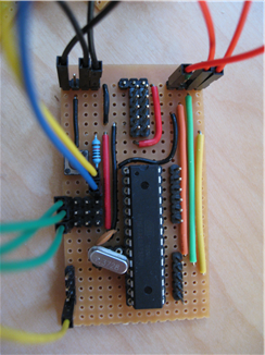
The servo controller itself ended up being on a board which could probably be used for all manner of ATMega projects. The board contains header pins for the I/O lines that I need, a reset button, a socketed crystal, power buses and an ISP programming header. About the only thing that’s been specially done for the servo controller application is the fact that the I/O multiplexor address lines have 4 banks of headers broken out so that I can connect multiple I/O boards to the servo board easily. The board is pretty much complete and works well; I’m especially pleased with the ISP header as it was quite tricky to fit onto the board due to the connections required. All that’s currently missing are the caps on the clock lines, but the board works pretty well without them and they’re currently on order and there’s space on the board for them. Note that a slight physical design error meant that the single power and ground pins that I had intended to use were in the way of the ISP plug. I cut those off and replaces them with the longer header strips which work better as they give me somewhere else to get a power or ground connection from…
ServoControllerBoard.png
Once all of this was done I tested things and then swapped out my Max232 board for the Sparkfun regulated XBee breakout board and connected the XBee in place of the hard wired RS232 connection. This worked well and left me with a set of boards that only required a power line to tether them; the battery system is on my list of things to work out. Unfortunately I managed to brick one of my XBee’s. I’m still not quite sure what happened but I think it could have been either a spike on the 5v power line or a 5v splash onto the XBee TX line. The Sparkfun board regulates the 5v supply to the 3.3v required by the XBee and uses a diode to drop some voltage on the RX line so that the 5v TTL logic line from the ATMega is dropped to be within the tolerances of the 3.3v logic required by the XBee but it leaves the TX line unprotected (the 3.3v logic levels of the XBee are enough to register as valid levels for the 5v side of the circuit but if 5v were applied to it then it would cause problems…). Ideally I’d like to put together a more robustly protected circuit with level shifting on both RX and TX lines but right now I don’t quite know how to do that (even the AdaFruit XBee board only level shifts the input lines and leaves the output lines vulnerable). I expect I’ll use the Sparkfun level converter board when I get a replacement XBee.
With my electronics off of my breadboard I began working on the servo sequencer. This will deal with moving the servos in sequence to create various walking gaits. Once I’d played with a simple sequencer I decided that I needed to solve the ‘hip joint’ problem once and for all and then build more legs; after all,sequencing a single leg isn’t that much fun.
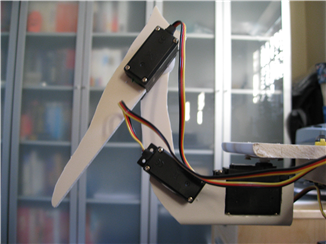
The prototype leg that I built way back at the start of this project has always been weak as far as the hip joint is concerned. The need to connect two servos at right angles using only a piece of plastic window board creates many problems. My experiments with using metal brackets made from Mecanno failed as the pieces I had were insufficient to hold the servos correctly. Unfortunately I don’t currently have access to the custom machining facilities that this guy has access to, so custom aluminium parts are out of the question. In the end I spent a lot of time with a craft knife and pieces of window board and eventually came up with a design that seems to work; at the very least it’s stronger and more reliable than the original leg. The design is based on the custom aluminium pieces from the A-Pod hexapod. I expect it will still change somewhat but it’s enough for me to move forward…
Legv3.0.png
I now have 6 Hitec HS-645MG servos on order along with a couple more XBee radios and a few more bits and pieces. The plan is to build two legs with the new servos and get the sequencer working. Once I get to this point I should be able to purchase more servos, carve more legs and move to a full six legs. Perhaps this hexapod project will actually have a hexapod before we reach our one year anniversary in April.

